Tandy Turbo Beetle ESC swap
Tags: rc tandy tandy-beetle electronics reverse-engineering quicrun atcomi アトコミ
The Tandy Turbo Beetle’s original Atcomi electronics merge a radio receiver and motor speed controller all in one very dense single-sided board. In this part of the project, I’ll figure out what each wire does, and install a Quicrun 1060 ESC alongside a Flysky radio receiver to get this car’s motor usable again.
An ESC, or electronic speed controller, drives the car’s motor in response to a throttle input. Usually, that input is a PWM signal that comes from the radio receiver.
To make things a little more confusing, the ESC also usually provides the power supply to the rest of the car. It’s responsible for doing the voltage regulation from the batteries down to a level that the servo, receiver, etc expect. This function used to be a whole separate component, called a “battery eliminator” or BEC, but it’s been integrated into every electronic speed controller I’ve ever touched.
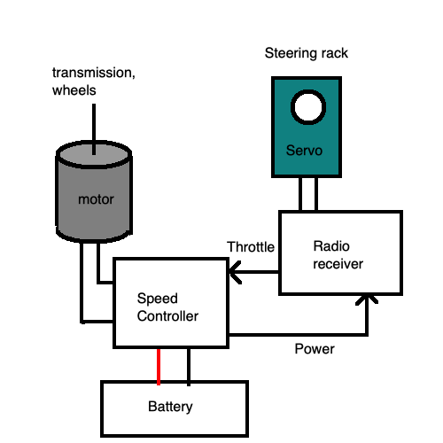
As for the motor itself, the speed controller drives it using what is known as an “H-bridge” arrangement. H-bridges are as old as the seas, and in an RC car application, they’re responsible for switching the power on and off (in both directions) to a brushed DC motor.
Brushless motors have a whole other thing going on, but since the Atcomi Beetle is from the 80s, we can safely assume that the little motor tucked into the rear axle is brushed. I only have one brushless motor on hand and the ESC for it has been damaged, so we’ll leave that project for another car.
Why do this?
The simple answer is that the stock Atcomi electronics are pretty proprietary. Its radio runs on a 40MHz frequency, and I don’t have the original transmitter.
Not only that, but a modern ESC and receiver have a lot of benefits. For instance, the Quicrun has built in braking, as well as compatibility with LiPo batteries. Of course, I’m not going to be running LiPos on this car, since I have barely any room for them, but it’s nice to have the option somewhere down the line if I decide to swap this ESC into another car.
Packaging
To start, I put some poster putty on the bottom of the body and squashed it down onto the chassis to figure out just how much clearance I would have between the top of the Atcomi PCB and the bottom of the Beetle body. It turns out that I do not have much clearance at all.
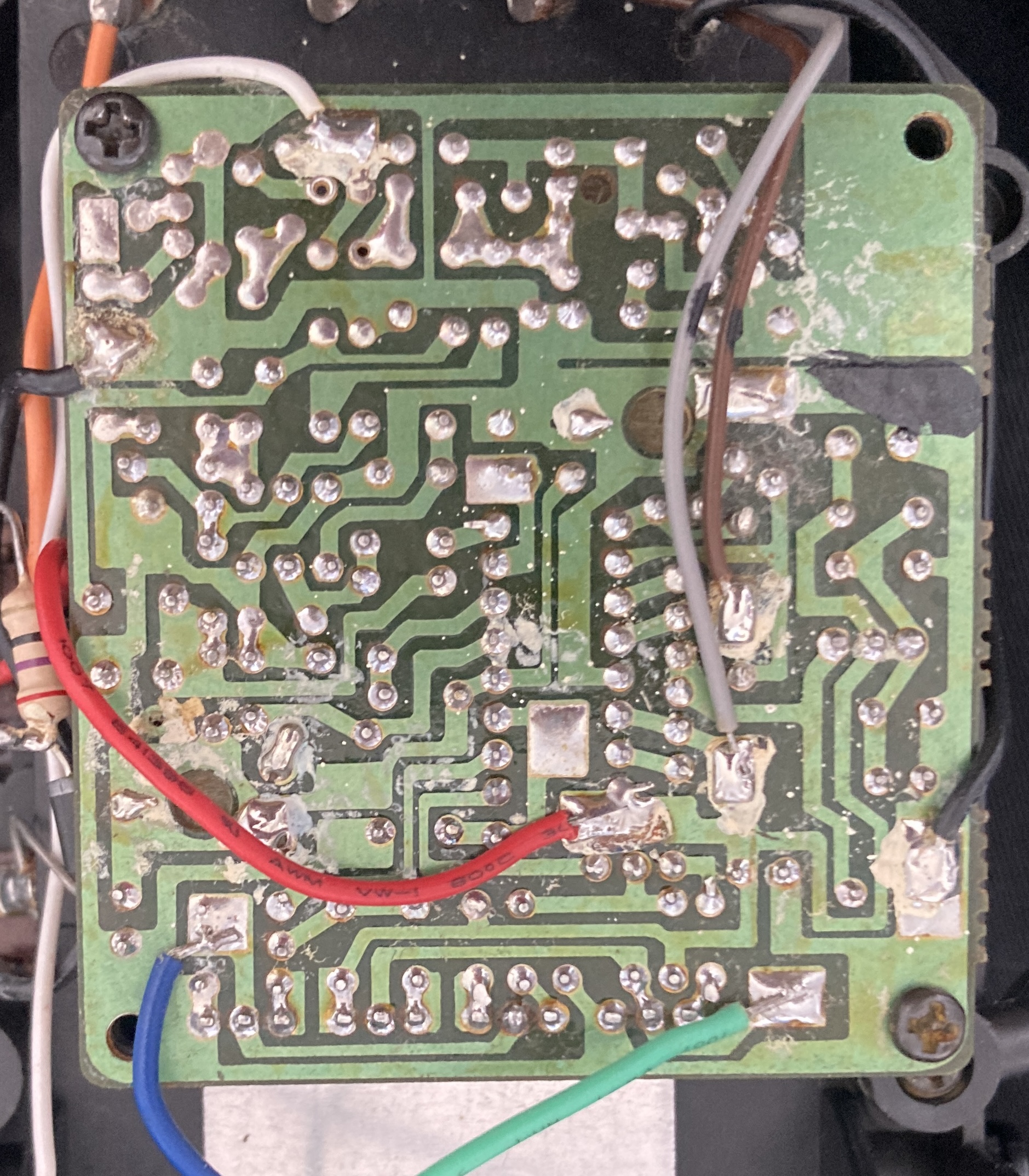
The original PCB is flipped over, so that the taller components don’t interfere with the body, and only the underside of the board is visible when you take the body off. I made a quick note (and photo) of where each wire went, and started my reverse-engineering journey. By using my multimeter’s continuity test mode, I was able to figure out where each wire went.
| Wire colour | Function |
|---|---|
| Orange | Battery + |
| Black | Battery - |
| Red | Switched +12V from battery |
| Grey | Servo ? |
| Brown | Servo ? |
| Green | Motor - |
| Blue | Motor + |
| White | Antenna |
There is one wire pad underneath the OKI motor controller (more on this later) which doesn’t seem to be used. I marked that one with an “X” so I wouldn’t accidentally attach anything to it.
There’s no guarantee that your Atcomi Turbo Beetle will use the same wiring, so take a hard look at the picture up above before you start throwing things together.
Board removal
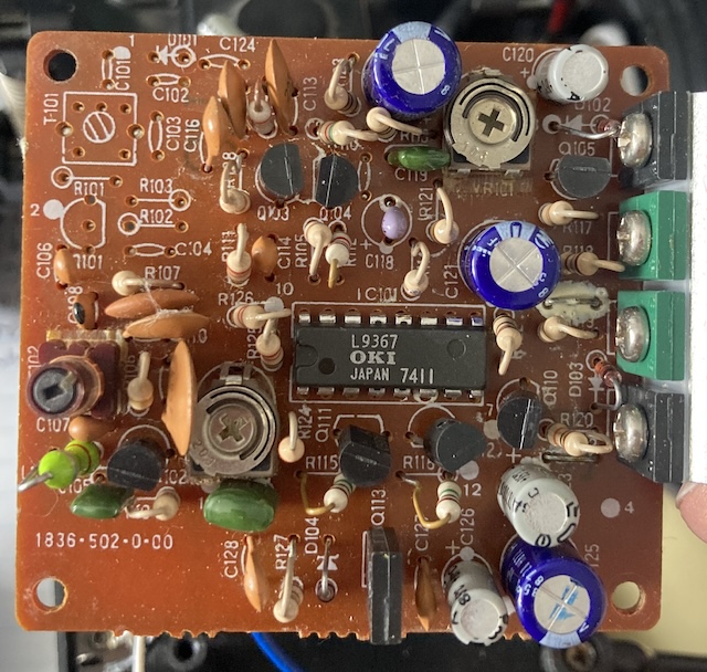
After desoldering all the wires (a stinky job!) I was able to unscrew and remove the PCB. All the components are on the other side, and there’s also a part number: 1836-502-0-00. I did a quick web search, and found nothing.
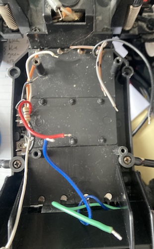
There’s not much left in the car once the board has been removed.
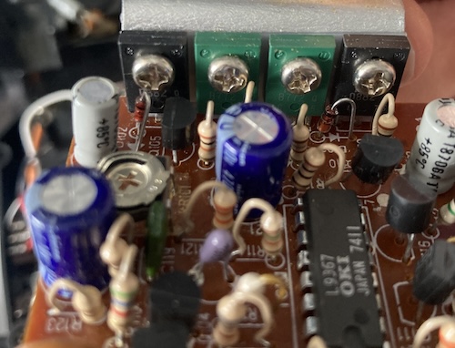
This board has some really big diodes and transistors, which are almost certainly for motor control. Because these old-school parts get really hot under normal function, they are bolted (and pasted) to a thick aluminum heatsink that helps dissipate the heat so that they can last longer and stay in their optimal temperature range for maximum power.
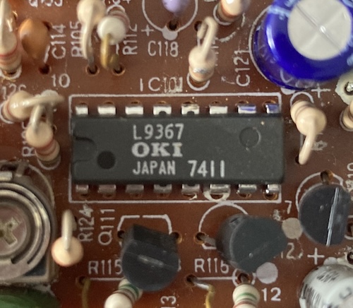
IC101 is the star of the show, or at least the most complex component. It’s an OKI L9367, which is also used on the Tamiya Super Sabre and the Radcon Wild Fox. Probably, this is a “datasheet build” where everything is exactly as OKI specified.
The date code seems suspicious. I don’t think this was made in the 11th week of 1974, unless OKI made a bajillion of these and had been selling them for literal decades. That wouldn’t be too surprising, since I suspect the demand for “remote controlled toys” has been pretty high for a long time.
Update: bsittler chimed in to mention that this is likely a “Japan Integrated Circuit” date code system. In that case, 7411 would indicate that it was manufactured January 1984. Thank you for the update.
Quoth the poster “Vegeta:”
The second character of the code is the last digit of the year of manufacture, the third character of the code is the 1-9 month production of January-September, the X - October, Y - November and Z - December.
Perhaps because it’s such an old Japanese part, I had trouble finding an OKI datasheet, but kept getting steered towards ST Micro. I’m not sure if they’re a second source for this part, or if they bought the product line from OKI. Changing my query to “Tamiya L9367” and “タミヤ 9367” produced some blog posts about doing fun things with these chips, including this neat Japanese blog post about replacing the L9367 with a microcontroller and this post that partially figures out the pinout and motor H-bridge configuration.
After doing some initial tracing, I decided that I don’t want to dissect the board in this post, so we’ll save that for the future. Let’s proceed to powering and wiring the car.
Batteries
After flipping the body over, I did a quick measurement with my digital calipers to determine that I had, at most, 25mm of room to build my electronics in. That meant I would probably not be able to go with my original plan of sticking a Traxxas battery pack inside this machine.
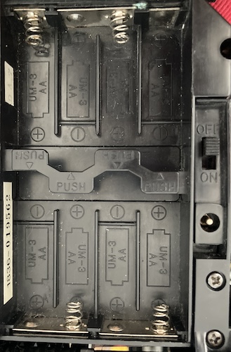
That’s okay, because the Beetle is already configured to accept (and charge!) eight AA-sized rechargeable batteries in series. If memory serves, it was designed to charge NiCd batteries. I’ll probably be using Ikea LADDA 2450mAh batteries in this system, which means I might have to remove the blocking diode and current-limiting resistor that make up the entire current charging “system.”
For now, I’ll simply disconnect the charge port and charge the batteries outside of the system using a dedicated wall charger.
Since the Ikea batteries are only 1.2V nominal instead of the 1.5V of an alkaline AA, the actual voltage the ESC will be seeing is 8 * 1.2V = 9.6V. Based on reading the manual, this will be perfectly fine with the 1060; it says it’s fine for “5-9 cell NiMH.”
Throttle wire-up
The Quicrun ESC has 4mm bullet connectors on it, plus wires big enough to fill those. The old motor certainly does not have any wires that thick coming out of it. It was at this point that I realized I probably did not need to have bought a 1060; I could have been fine with one of those eight-dollar heatshrink bodge jobs that are all over AliExpress.
That said, I can always remove this and put one of those in later if I find something else more deserving of the 1060, and the Quicrun isn’t really that much more expensive if you squint and have a hazy concept of what “numbers” are.
I grabbed some Amazon connectors and got started soldering the motor wires into the bullets. This was a bit of an effort, because the original wires had taken a set over the years, and weren’t really helping me get them into the connector and flow the solder at the same time. Ultimately, I was somewhat successful, but the heat shrink sure doesn’t look great. Good thing we have electrical tape.
At this point, I had no idea what the green and blue wires did, other than that they went to the motor. Since they’re on bullets, I can at least switch them if I got it backward.
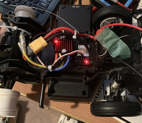
Because it had to go somewhere, I mounted the ESC up near the front of the machine using a loop of masking tape. Originally, I used two-sided Gorilla Tape, which is always an infuriating experience until it finally decides to stick. This left me a lot of room for the other components and for wiring, and to my surprise, the body even cleared the extra-tall jumper blocks on the Quicrun.
For wiring the batteries to the ESC, I chickened out and simply soldered an XT60 pigtail to the original battery contacts. This was a little hard, because the XT60 pigtail I picked from my stash was 12-gauge, which meant the wires were thick and hard to put where they needed to go. Ultimately, I succeeded in the world’s worst wiring configuration, and I was even able to put the body on with some effort.
For the main power switch, I ended up using the one from the ESC. I removed the original power switch from the frame, and cut out the diode-and-resistor “charge controller” from the DC jack. The new power switch is waterproof, but the lever on it is much shorter than the old switch. For now, I’ll use a toothpick to turn it on and off.
Throttle test fire
To provide power, I hooked the car to my bench power supply and dialled it in for nine volts. I figured that if anything went wrong, it at least wouldn’t be because of overvoltage.
I flipped the switch on the Quicrun, and everything powered up. I got a cute little beep from the Quicrun and then it started to flash its light. No throttle response was observed. After checking the Quicrun manual, I realized that I had plugged the ESC into the “VCC” pins of the Quicrun and not the throttle input, Ch2, as expected.
I tweaked that, and suddenly I had throttle. Sure, it was noisy (sounds quite dry in there) and not especially intimidating levels of torque (it’s in high gear) but I had a working throttle. Nice! I had fun revving the receiver and watching the wheels spin, and fun is what this hobby is all about.
Of course, the throttle was backwards, so I quickly switched the bullet connectors going into the Quicrun, and now I had correct working throttle. Nicer!
Servo wiring
Now to figure out the steering. I only saw two wires pointing out of it, which made me wonder if it was some kind of servo incompatible with the receiver, which seemed to expect a 3-wire servo. To make sure it wasn’t sneaking a secret ground or power wire, I took the whole front end off the car, and found that it was not.
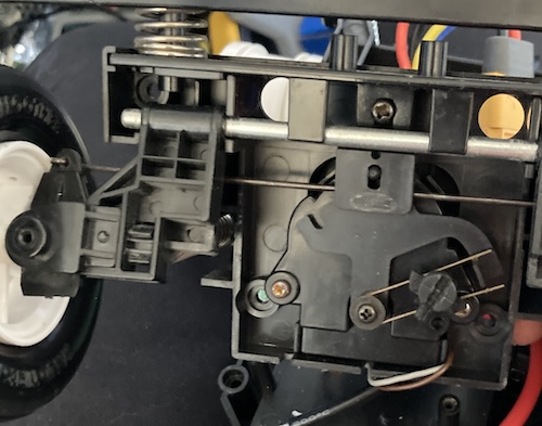
Two wires made me wonder if this was even a servo at all, or if it was simply a motor that was run positive or negative until it hit the limiter. The presence of the bipolar capacitor on the top of the case seemed to indicate that it might be.
Indeed, once I pulled the front end off, that was exactly what the problem was. It seems like a lot of toy-grade RCs, especially from the 80s, liked to do this configuration instead of what is known as “proportional” steering. In other words, it can either point forward, full left, or full right, with nothing in between. Certainly, this could work, and I could make an adapter circuit for it that works with the receiver, but I think it’s more fun if I retrofit a real servo in.
The next step is to figure out how to mount a servo to this sucker, and get the steering to work. This will need a little bit of research, and probably a lot of cutting and trimming of plastic. Stay tuned!
It’s so close to Beetle-bashing season, I can taste it.